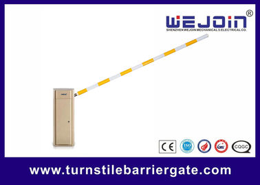
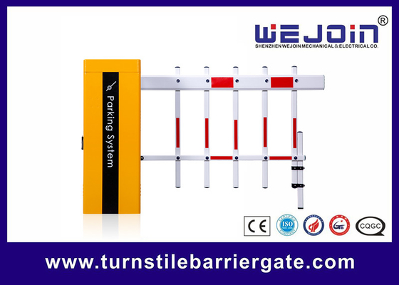
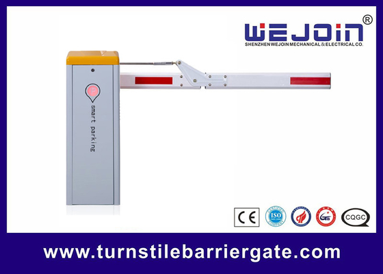
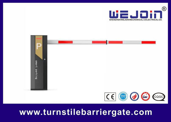
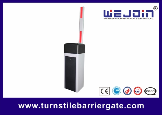
High-Grade Residential Area Access Control Black Color 6m Straight Aluminum Arm Barrier Gate
Parking Barrier Gate Technical Data
|
Model
|
WJDZ04VF (speed 1.5~6s adjustable)
|
|
Running Speed
|
1.5s-6s
|
6s
|
6s
|
6s
|
6s
|
|
Boom-Type
|
Straight
|
90° Folding
|
180° Folding
|
2 Fence
|
3 Fence
|
|
Max Boom Length
|
3-6m
|
5m
|
4m
|
4.5m
|
4m
|
|
Housing Dimension
|
336*325*1030MM, 335*285*920MM
|
|
Input Voltage
|
AC100-265V
|
|
Frequency
|
50/60HZ
|
|
Motor Voltage
|
DC24V
|
|
Enclosure Rating
|
IP54
|
|
Working Temperature
|
-30℃~ + 70℃
|
|
MTBF
|
4000000 times
|
|
Traffic Flow Application
|
3000 times/ 24 hours
|
|
Max Motor Power
|
180W
|
|
Max Motor Speed
|
500r/min
|
|
Max Torque
|
260N.m
|
Parking Barrier Gate Functions & Features
1. Motor Functions & Features Self - developed DC24V brushless motor, with stable and reliable worm gear and planetary reduction transmission structure, large torque, and wear resistance.
2. Control System Functions & Features DC variable - frequency control system, precise control, more flexible running, less mechanical impact and longer service life.
3. Auto - reversing on Obstruction Functions & Features Sensitive, responsive, safe and reliable.
4. Item Control Panel Functions & Features Large LCD screen display, English visual menu, simple maintenance and easy operation.
5. Remote Controller Functions & Features 433MHZ, simple to add remote controllers.
6. Operation during Power - off Functions & Features Turn the handwheel or lift the boom manually to realize the boom up and down, and it can also be powered by a DC24V battery, or open one time by a super capacitor backup.
7. Motorcade Passing, Counting, Auto - aging Test, Delay Auto - closing, Relay Signal Output, RS485 Communication Functions & Features Support
8. Loop Detector, Infrared Photocell, Radar Functions & Features Optional
9. Warranty Period Functions & Features 24 months for motor and control board
Mechanism Installation Direction Change
This barrier mechanism can be both left-installed and right-installed. The users can change the installation direction according to the actual situation. We will take the left-installed barrier mechanism as an example, and the operation steps for changing to the right-installed are as follows:
1. Take out the 10MM screw by turning 8MM Allen wrench counterclockwise
2. Push out the boom holder by turning wrench clockwise with a 14MM*150 screw
3. Turn the mechanism 180 degrees vertically
4. Put the mechanism into the cabinet
5. Assemble the boom holder back, and fix the 10MM screw by turning 8MM Allen wrench clockwise
Barrier Gate Warranty and Service Items
1. Free service is offered for component parts in one year warranty time. (not includes the barrier boom or remote)
2. Lifetime service with charge accordingly.
3. Technical questions are supported.
4. The below items and situations are not included in the range of free service:
4.1. The user does not follow the instruction and cause any damage of the product.
4.2. The power supply is not stable, over the range of permitted voltage or not accordant to safety electric using standard.
4.3. The user installs or uses the product in wrong methods, cause damage to the appearance of product.
4.4. Natural disaster causes damage to the product.
4.5. Warranty time is over.
4.6. Service items are out of our promises.


 Your message must be between 20-3,000 characters!